Common Mistakes in Solar Site Surveys
The U.S. Department of Energy shows that so-called “soft costs” including permitting, design, and installation processes make up a significant portion of total system cost and are heavily influenced by…

Insights
A 2024 SEIA report found that over 1 in 5 solar inspection failures are linked to grounding issues many of which start with a misunderstood or overlooked PV system grounding diagram.
For installers and designers, reading these diagrams shouldn’t be a guessing game. They're critical for safety, NEC compliance, and smooth inspections — yet often skipped or rushed through.
This guide breaks down how to read a PV system grounding diagram in under 10 minutes. Whether you're reviewing a plan set or prepping for an AHJ inspection, these tips will help you avoid costly mistakes.
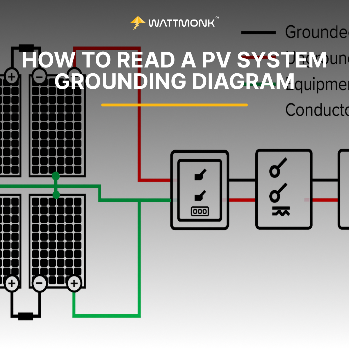
A PV system grounding diagram is a dedicated part of the solar plan set that shows how all metallic parts of the system are electrically connected to the earth or a grounding point. Its purpose is straightforward: to ensure safety by preventing shock hazards and reducing the risk of equipment damage during a fault or lightning strike.
But beyond safety, grounding is a code-mandated design element. These diagrams are required by local Authorities Having Jurisdiction (AHJs), utilities, and financiers during plan reviews, inspections, and approvals.
You’ll typically find the grounding diagram near or within the electrical sheets of your plan set. It highlights:
Grounding in PV systems isn’t just best practice — it’s a strict code requirement under the National Electrical Code (NEC). Whether you’re designing or installing, understanding the latest grounding rules is critical for passing inspections and avoiding rework.
Here are the key NEC articles and updates relevant for PV grounding as of 2025:
Once you open a PV system grounding diagram, your goal is to quickly verify that the grounding is complete, code-compliant, and clearly labeled. Here’s how to do:
Start by checking the diagram legend. Look for standard grounding symbols:
Installers often skip this step, but symbols vary by drafter or firm. Always match what's on the legend with what appears in the diagram.
Look for the grounding electrode conductor — it should run from the inverter, combiner box, or disconnect all the way to:
Check that the conductor size (often #6 AWG copper) and path comply with NEC 250.64 — especially if there are splices or bends.
Ensure metal racking, module frames, and enclosures are:
Inspectors often flag bonding jumpers that are missing between rows or not torqued to spec.
Confirm:
Double-check if a separate ground is needed for a detached structure.
Most grounding diagrams include textual notes that clarify:
These notes often address what can’t be shown clearly in the line diagram, so don’t ignore them.
Interpreting a PV system grounding diagram isn’t just about following lines — it’s about understanding how those lines translate into real-world safety and compliance. Here's how to connect what's on paper to what happens in the field.
Every point where grounding conductors connect — inverter chassis, disconnect enclosures, combiner boxes — must be:
Diagrams often mark these points with notes or annotations. Skipping over them in the field leads to common grounding failures.
The size of your GEC or EGC affects its ability to carry fault current safely. Oversizing isn’t a problem — but undersizing definitely is.
Use the diagram to:
While NEC is national, local AHJs often interpret grounding rules differently. Wattmonk’s plans are jurisdiction-aware — so if your county requires a separate ground for detached garages, or only accepts CAD-welded connections, it’ll be in the diagram and notes.
Grounding might not be the flashiest part of a solar install, but it’s one of the most critical — and most scrutinized. A single oversight in your PV system grounding diagram can mean delays, red tags, or even safety risks.
The good news? You don’t need to be a code expert to read these diagrams confidently. Once you know what to look for — grounding paths, bonding points, conductor sizes, NEC references — it becomes second nature.
At Wattmonk, we’ve built our solar plan set service around helping installers like you stay compliant, pass inspections faster, and reduce rework. Every grounding diagram we deliver is checked against the latest NEC codes and local AHJ rules, so you can focus on getting systems energized, not stuck in permitting.
Explore Related Insights
Dive into our meticulously selected articles that provide insights on sustainable practices and eco-friendly strategies for brands.